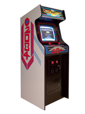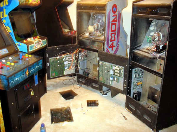
A few years ago when I lived in Denver, CO, I had this guy build me a Robotron 2084 from a bad Legendary Wings conversion. It was my very first video game and I paid him $600. I didn't really know what I was doing at the time, but $600 seemed like a good deal to me. Looking back, the guy was pretty much a hack and even though the game worked, he did a number on the wiring harness and some of the boards. The cabinet was in really rough shape, even the bottom front corners were rounded off pretty bad. That was almost twenty years ago and a lot of video games have filtered through the arcade since then. Unfortunately, I've sold or traded every game in this picture since then, which I deeply regret. Especially the Moon Patrol that's in this picture. It had 40 plays on it when I got it.
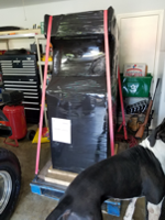
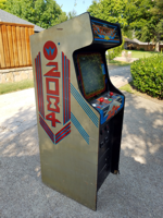
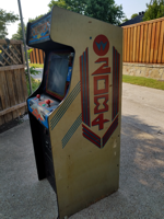
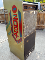
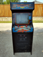
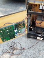
However, recently I was able to pick up a non-working Robotron in Florida off eBay for $500. Look like a steal to me since it was all original and all there. I used YRC Freight and had it shipped to Dallas, TX. After about a week it arrived and I came home to find it in the garage. Here are the pics I took the day I opened it up.
 |
 |
 |
 |
 |
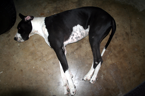
| Big dog approves! |
Nice wrap job |
The reveal |
Very dirty |
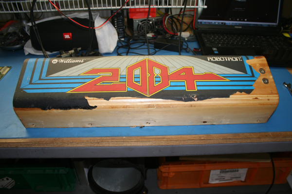
Back door is rotted |
 |
 |
 |
 |
 |
| Control panel ashtray |
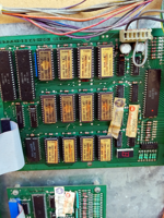
Original boards |
36 years of dust |
Matching serial numbers |
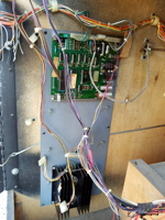
Nice fuse |
 |
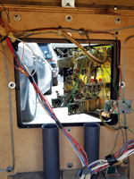 |
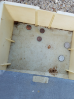 |
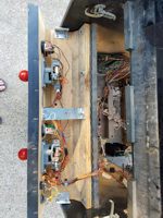 |
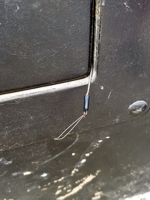 |
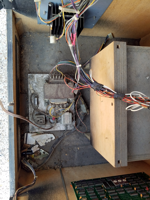
| Missing power board |
Hacked wiring |
Original coin tray |
Extra buttons |
Fishing hook |
| Control Panel | Power Block | G07-CBO Monitor | Boardset | Wiring Harness |
Control Panel - CP
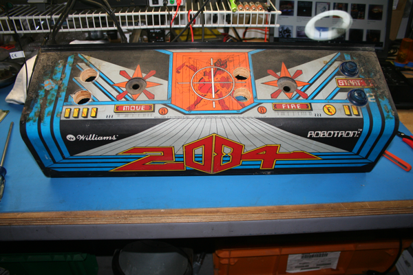
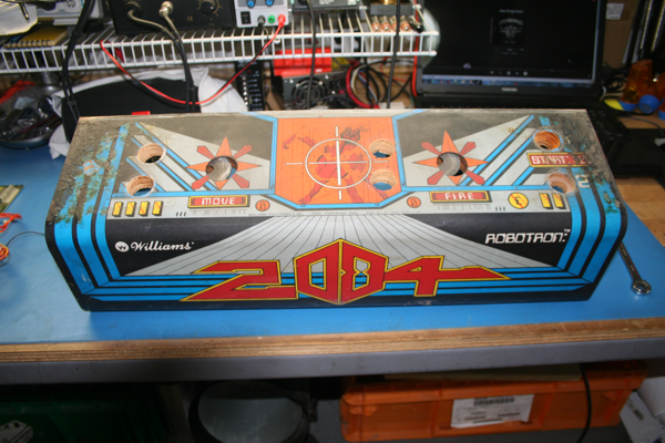
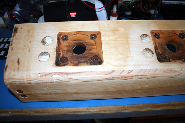
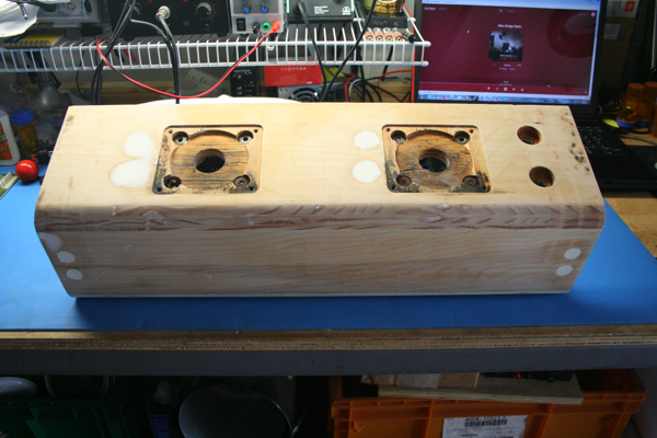
I think I'll get started on the control panel first. The grommets on both joysticks were original and completely dry rotted and falling apart. Some idiot also semi-converted this classic into a Choplifter and added four new buttons to the control panel and hacked up the wiring harness. What a shame. I'll have to fill these holes with some good quality wood epoxy like Abatron. This stuff isn't cheap but it's no joke either. It can completely replace wood and is super strong. But before we get to filling holes, we need to disassemble.
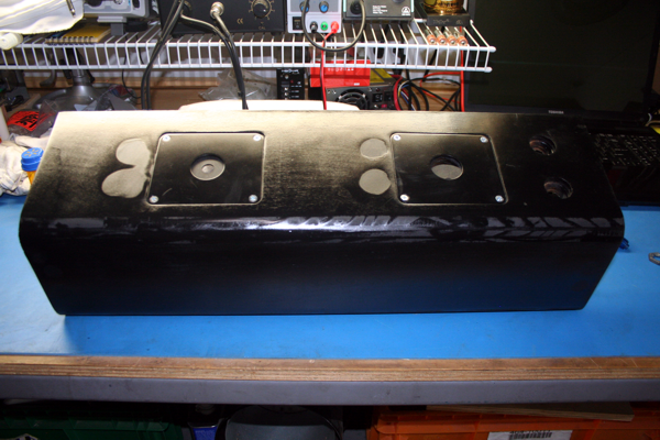
Somebody used this thing as an ash tray. It's completely filthy and the CPO is cracking. I also noticed the area (plate) that covers the Fire joystick has sunken a little and you can see how the CPO is cracked there as well. That area will have to be leveled. Joysticks and extra buttons removed.
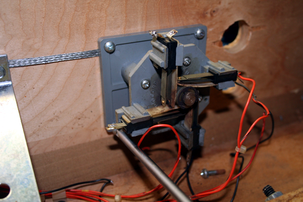
Unsoldering and removing the joystick base.
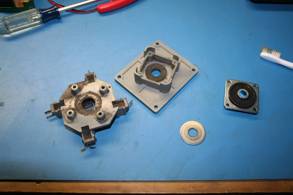
The joystick is removed and disassembled. I bought these new grommets from Arcade Shop. They make the world of difference.
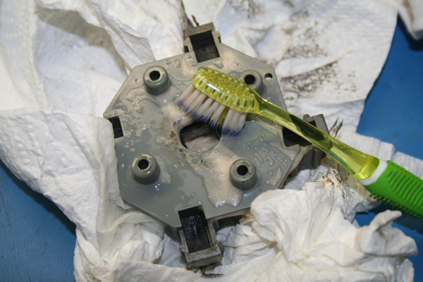
These joystick bases are completely nasty. A good scrubbing with Formula 409 will clean them up nicely.
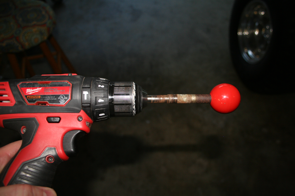
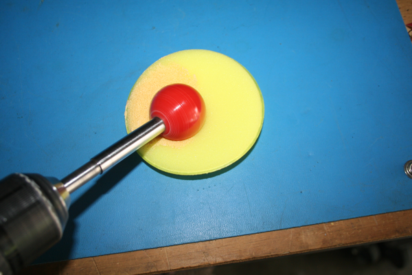
I secured the base of the joystick to my drill and set it on high. A high speed drill press works well for this procedure too.
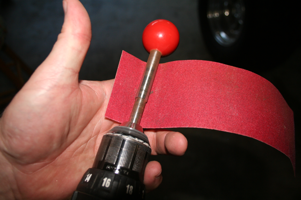
I used a sheet of 120 grit, then 220 grit, then 320 grit to sand the shaft of the joystick until it was silver again. These things were solid rust. I tried not to get too close to the red ball, but any marks can be polished out.
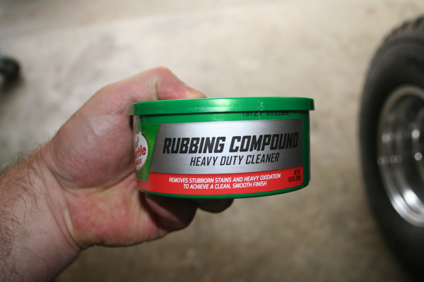
I picked up some Turtle Wax Rubbing Compound and polished the joystick shaft and ball at high speed.
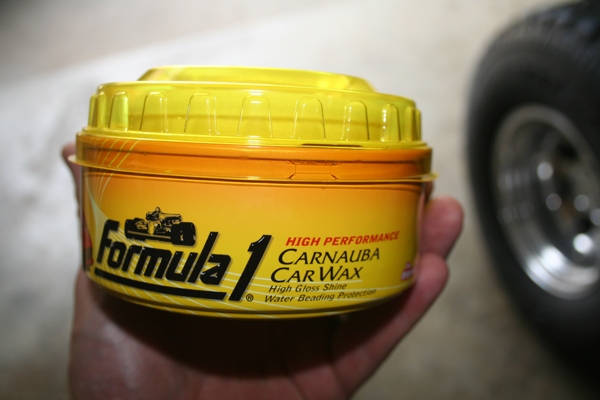
Then I used some Formula 1 Carnauba Car Wax to bring the red balls to a nice shine.
You don't have to use a lot, just enough to coat the entire ball.
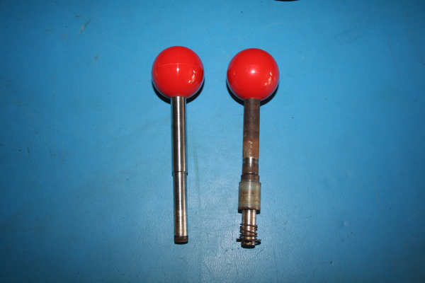
The one on the right is the before. You can guess which one is the after.
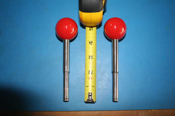
Both of them cleaned up like new and they're the correct length as well.
I think this control panel was used as an ashtray! LOL. Here it is with all the hardware stripped right before I peeled off the CPO.
And the peeling process begins. This is not a quick process, but you have to be patient.
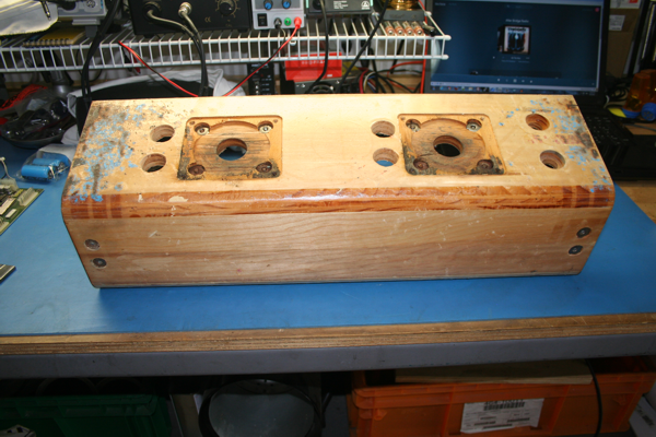
All the old CPO is finally removed. The cigarette burns go all the way to the wood. The adhesive is still on at this point. I'll need to apply some Xylene.
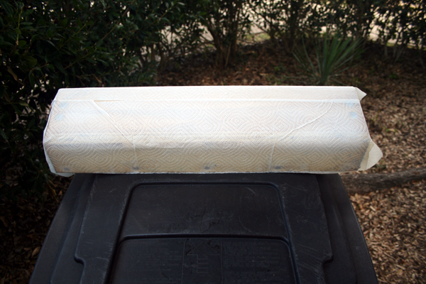
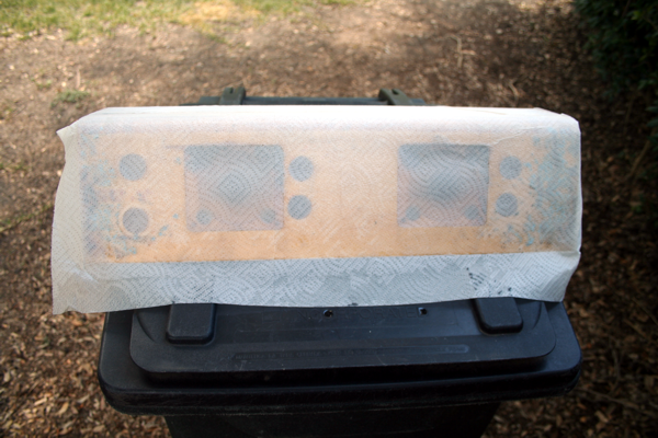
I covered the CP with paper towels. The adhesive sticks to paper towel very well.
I got this technique from Arcade Jason. Here's his video to show how it's done. I think he did it in his kitchen!! I would not advise that. I then poured Xylene all over the paper towels. You absolutely must wear gloves, safety glasses, and a mask/respirator when you apply the Xylene. You should do it outside or in a well ventilated area! This chemical is no joke and is very dangerous. It should be respected. I had to apply three coats and let it set about 5 minutes between each coat. But I did this in 97 degree weather and it evaporated pretty fast.
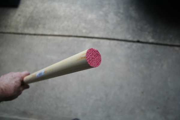
I picked up this wooden dowel at Home Depot to fill the four extra holes in the control panel some idiot added.
It is the exact diameter as the four standard cherry switch buttons that were added.
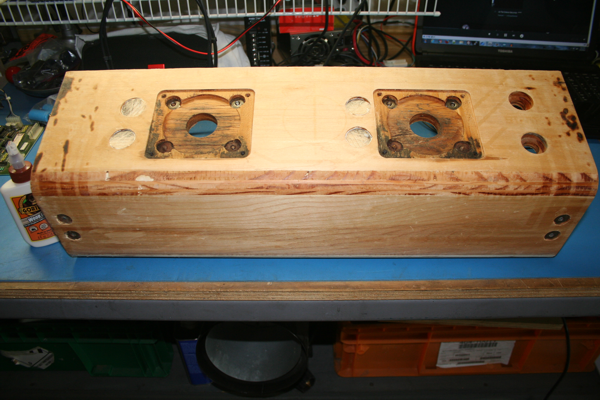
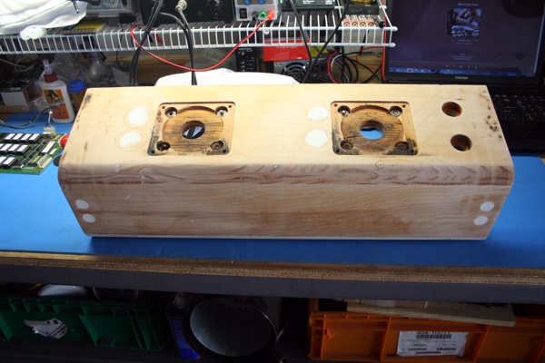
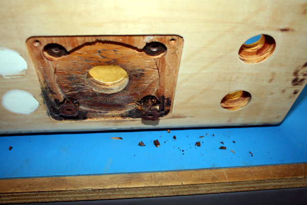
Here the control panel is completely void of any residual adhesive from the old CPO. I've also cut the dowel and filled the four holes where the extra buttons were. I've used Gorilla Wood Glue, but just about any wood glue will work. I'm not worried too much about appearances at this point, I just want to the get the holes filled. I have some stupid extra strong wood epoxy that I'm going to use to fill in any cracks or low spots in the CP. This will need to sit for a couple of days to ensure the Xylene completely evaporates and the wood glue really sets up.
I'm pretty sure that big dawg doesn't really care about Robotron Control Panels.
I got out my DA and hit the high spots where I put the dowels. I also gave the CP a quick light sanding all over.
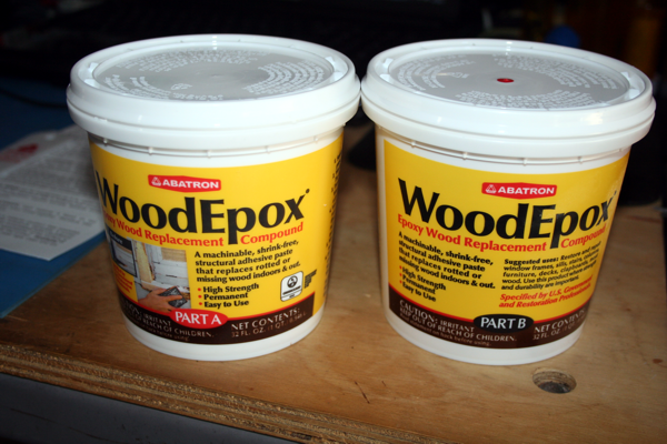
I've never worked with this stuff before but the reviews I've read on it are amazing. After this dries, you can cut, drill, sand, and nail this stuff supposedly. We're going to find out.
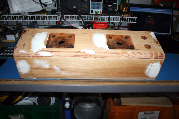
I filled all the low spots with the Abatron. Now I'll set it outside in the sun and let it bake for a while. It's going to rain tomorrow so I need to get this done before the weather gets here. I'll probably give this a couple of days to completely set in. The instructions say heat accelerates hardening, but the desired temp is 60-90F. Unfortunately in Texas summers, you don't get to chose temps below 90F. So it is what it is.
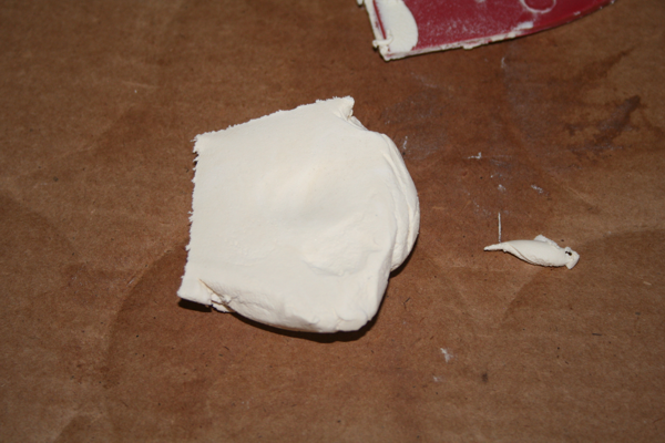
If you're thinking this stuff is like body filler (Bondo) or normal wood putty, think again. I've never seen anything like this before. To get the best results, I had to mix equal parts of Part A and Part B with my hands. I wore gloves of course. But it mixed to the consistency of a marshmallow.
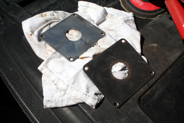
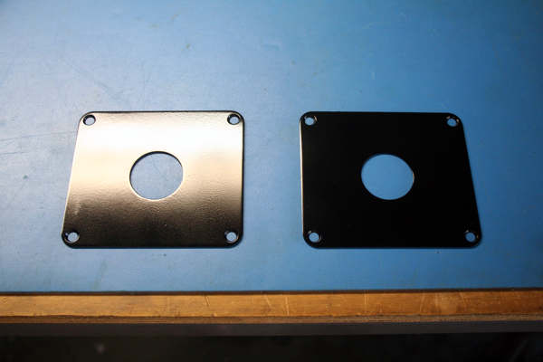
While I had the DA out, I might as well sand down the joystick guide plates. I've had these soaking in Xylene for over 24 hours to remove all the old adhesive. After a couple of coats of paint, I'll have these looking like new.
Two coats of fresh paint (semi-gloss) later and I'm 100% satisfied.
Here's the CP after the first sanding. I circled all the low spots and then put another coat of Abatron to fill them in. It will be a day or two before I sand again.
After a 2nd coat of Abatron and a 2nd sanding, I think I'm ready to replace some T-Nuts.
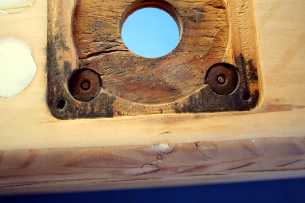
The bottom two T-Nuts at each joystick location are rusted pretty badly. Since I have this all apart, it only makes sense to replace them.
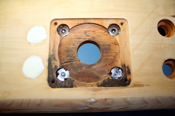
These T-Nuts were easy to take out. I just inserted the screw in the back of the T-Nut and tapped it with a hammer. They popped right out.
I only replaced the bottom two for each joystick. The top T-Nuts are not rusted and are still serviceable. I picked these T-Nuts up from Ace Hardware. They're 8-32, 1/4 x 23/32 Long Prong. 40 cents each.
Checking to make sure everything's flush with a ruler. I'm happy with these results.
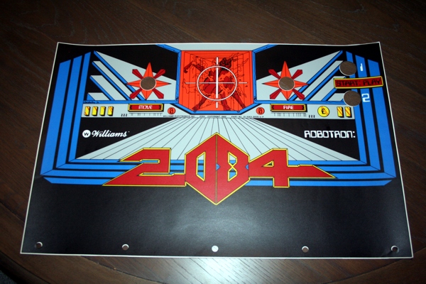
Some fine quality artwork from Darin Jacobs at Phoenix Arcade.
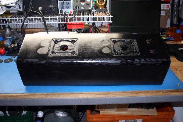
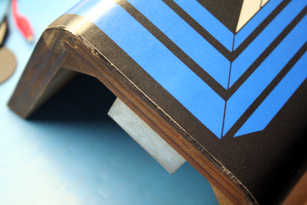
I shot a couple of coats of semi-gloss black on the CP because the edges of the Robotron CPO are black.
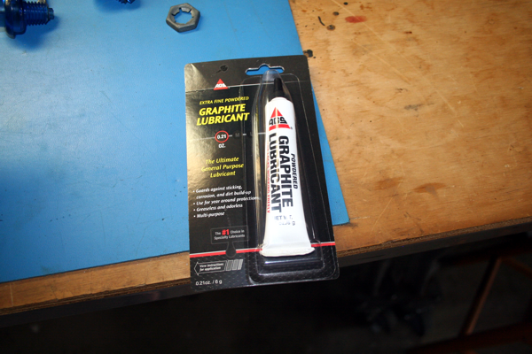
I went to Ace Hardware and picked up some graphite. I'll use this on the bottoms of the joystick dust covers as well as on the plastic washer(s) that's in the WICO joystick. This will just help with any friction and wear and tear on the plastic pieces over time.
Dustwashers and a couple of squirts of graphite and I installed the joystick guide plates.
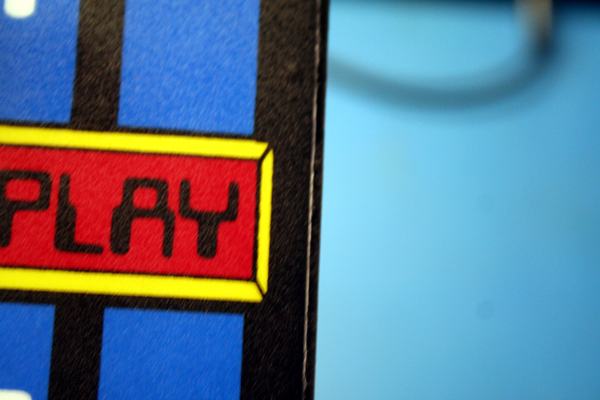
Now listen, I'm OCD. Bad. I tried stretching and stretching but I could not get the new CPO to reach both sides. It looks like it was cut a little too short. Here's a shot of the left side of the control panel. It's a good thing I painted the CP black.
Here's a shot of the right side of the CPO. It's off just as much. I painstakingly worked with this for over an hour and still could not get it to fit the width. It was defintitely cut too short.
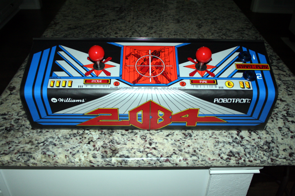
Here's the final product. My OCD keeps me from being 100% happy with this. I should have been trimming off some of the CPO from both sides, instead I was trying to get it to stretch to fit. This is frustrating to say the least. In the end, I'll probably remove this CPO and get another one, but for now this will have to do.....sigh.
Power Block
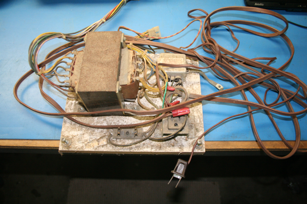
Nasty with a capital N! This thing has been collecting dust for over 36 years! Live from May 18, 1982. I love the way some Jackwagon wire-nutted a lamp cord on the end of the original cord. This game doesn't need a ground [insert sarcasm here].
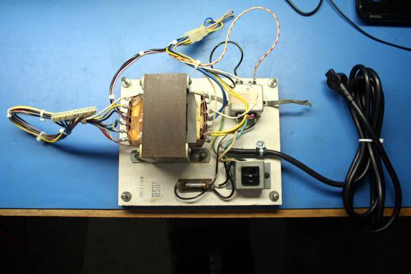
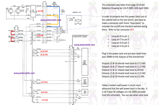
This actually cleaned up rather nice. I installed a new 3A SB fuse, a new power cord (with a proper ground), and built a connector that would feed power back into the transformer when it was out of the cabinet. You have to "simulate" the interlock switch or you won't get any power to the transformer. I'm probably going to shoot a coat of paint on the top of the transformer to retard any further rusting.
Click on this image to get a close up of how to test the Power Block.
G07-CBO Monitor
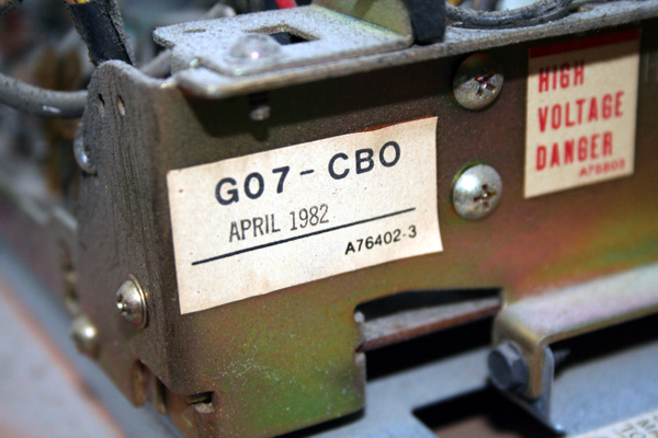
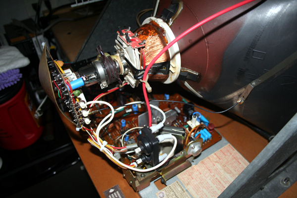
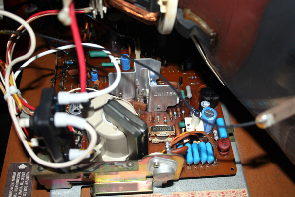
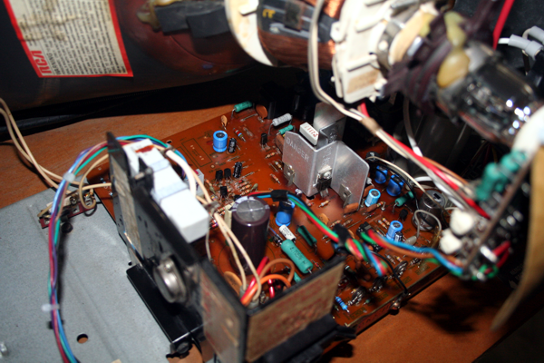
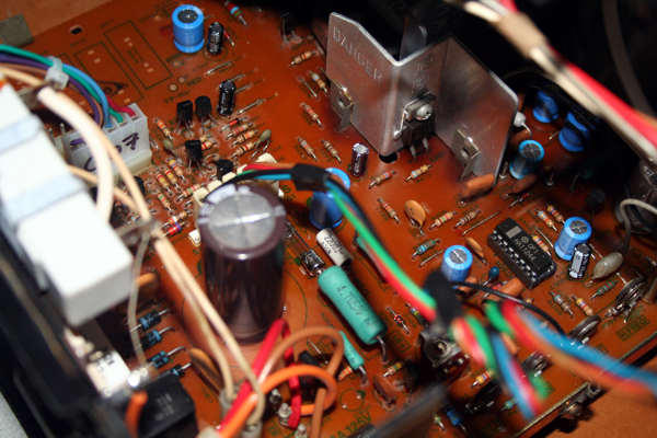
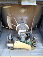
The original, unmolested, untampered with G07-CBO 19" monitor from a Robotron. Serial number matches the other boards in the game.
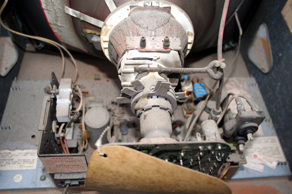
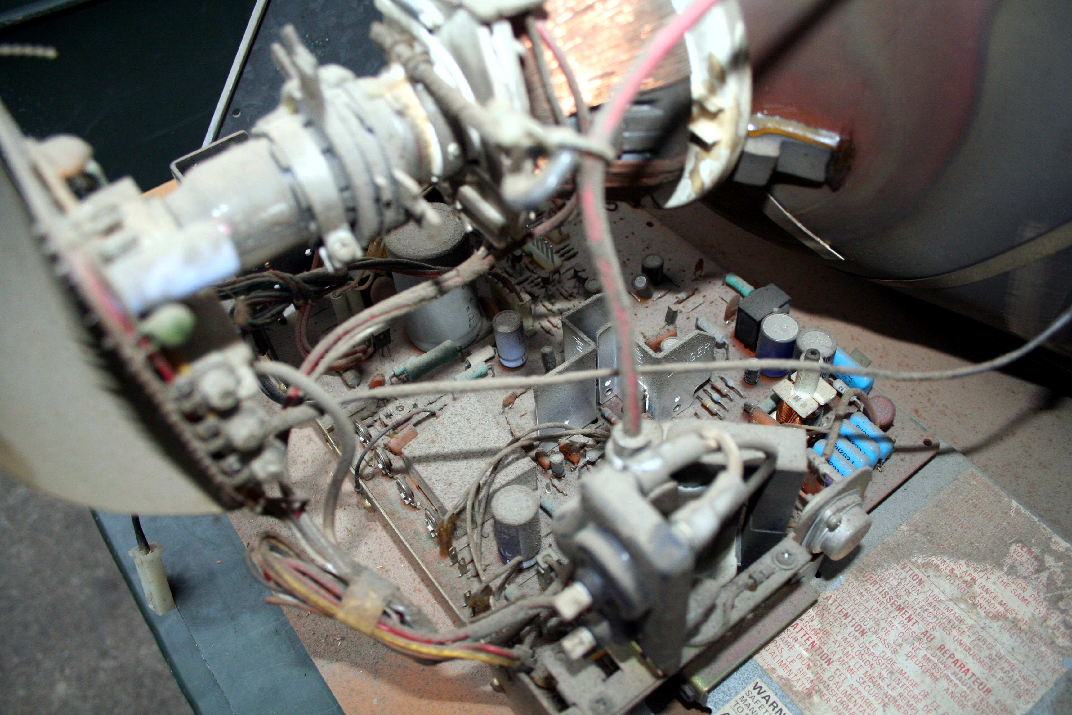
Nothing here but a pile of 36-year old dust.
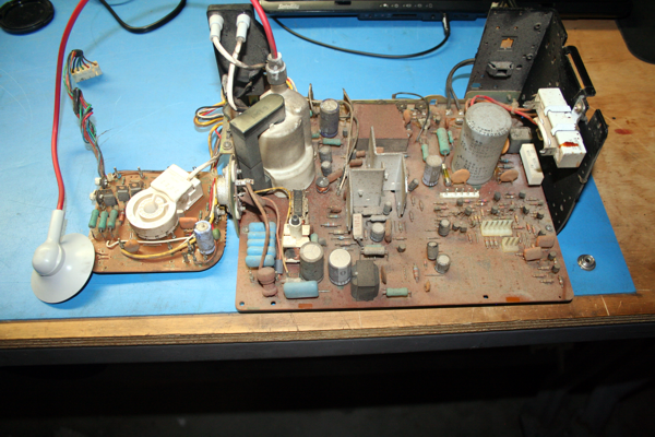
I pulled the boards out of the chassis to clean them up and do an inspection.
I put the entire assembly in the sink and sprayed it down with Simple Green and brushed it with a clean paint brush to clean up all the dust. A good rinse with scalding hot water later and we have a pristine clean PCB assembly for this G07. This will make it much easier to see the silk screened markings on the board. Plus I hate working on dirty boards.
Warning!! If you wet a PCB like I have done here, make sure you allow the board to completely dry before you apply any power to it. I let this bake in the Texas sun for a day after I cleaned it and then let it sit on the workbench for a couple of days for good measure.
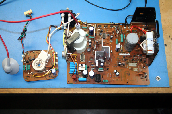
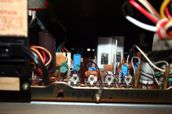
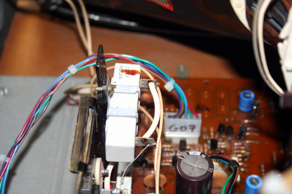
I think this G07 cleaned up really nice. Here's a pic of everything put back together. I did a complete cap kit, installed a new flyback, installed and socketed a new IC501, put in a new HOT, installed new axial fuses at F901 and F902, and installed new resistors at R314, R317, and R908. I'm really happy with these results and how it all turned out. I didn't take a bunch of pictures of me putting in a cap kit, there are tons of videos and how-to's on the internet for you to reference. However, if you have any questions, please send me an e-mail and I'll do my best to help. I also put together a cap kit map for your use. You can download it here.
I ordered one, but did not install a new horizontal width coil. This one is functioning and looked pretty good after I cleaned it up.
It is extremely important to insure you have a good B+ voltage (120VDC). To check (and adjust) the B+ voltage, put the black (negative) lead of your DMM on the monitor chassis. Put the red (positive) lead on the ceramic resistor on the left side of the chassis where the white wire is soldered to the resistor. Set your DMM to "Volts - DC" and make a voltage measurement. Adjust the B+ potentiometer until you get a 120VDC reading. When I started this procedure, my B+ voltage read 99VDC. Adjusting to 120VDC made the picture look 100% better.
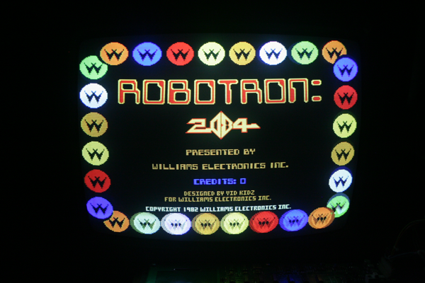
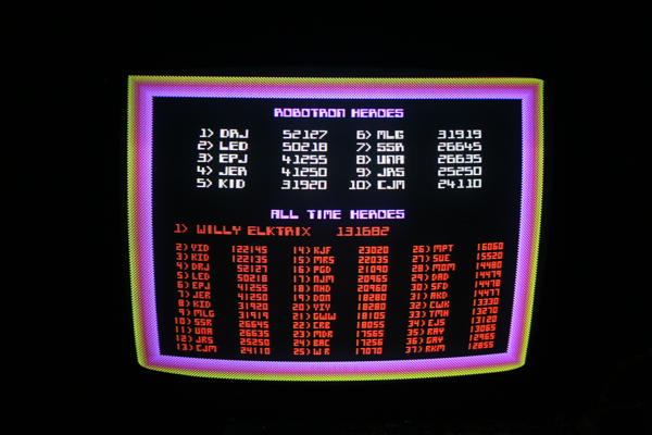
I got rewarded with a really nice G07 picture.
With a few small tweaks, this baby is ready to go in the Robotron cabinet. Now that the monitor is done, we'll focus on the boardset.
The Boardset
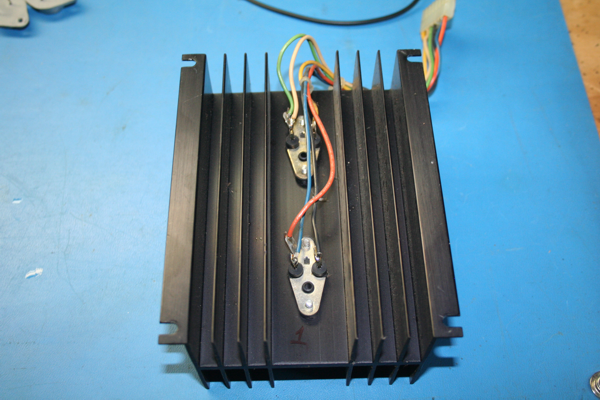
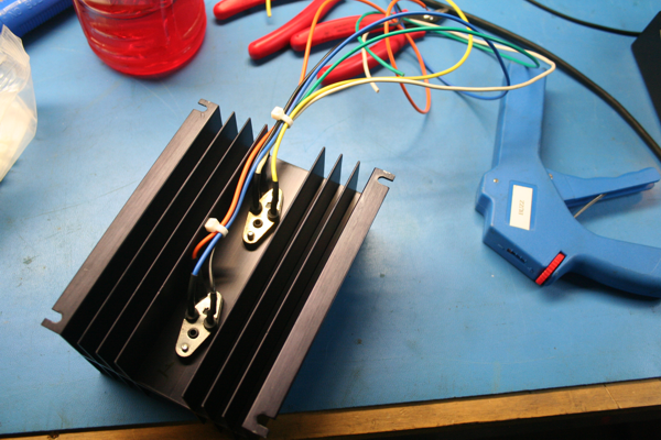
The original heat sink. I'm going to replace these transistors and rewire this heat sink. I want this to be rock solid.
New 18AWG wire, new zip ties, and new connector.
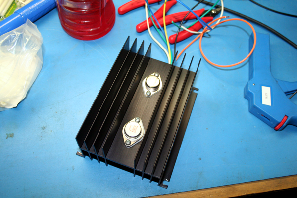
New transistors.
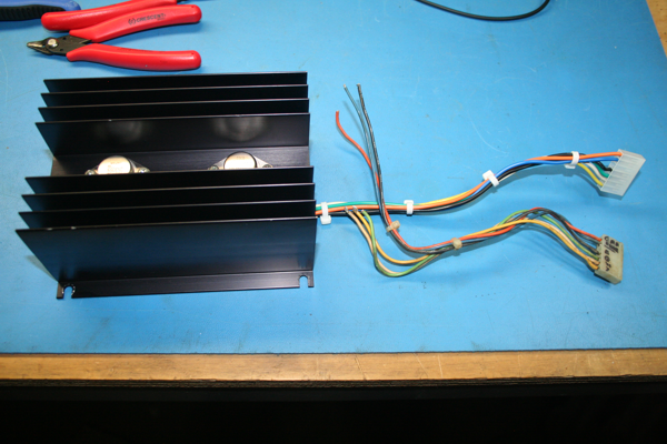
A much needed new harness (the old beside the new).
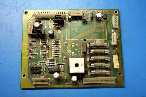
I pulled this old power board from a box of boards I had. It has some burnt connectors and the BR1 really cooked this board. Let's see if we can bring it back to life.
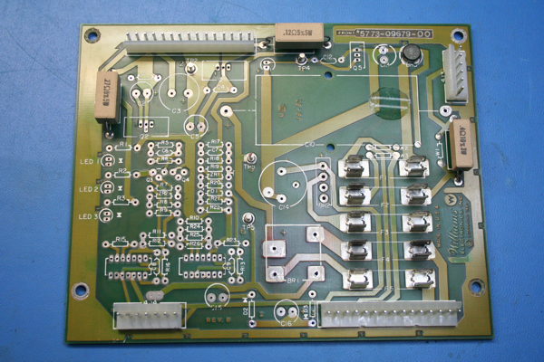
I literally took everything off this board except the three ceramic wire wound resistors. Those connectors are new.
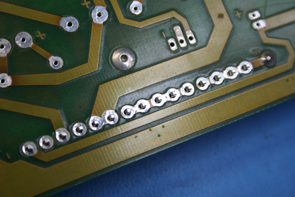
The Hakko FR-300 desoldering gun I have is the best I've ever used. Look how clean it made these pads.
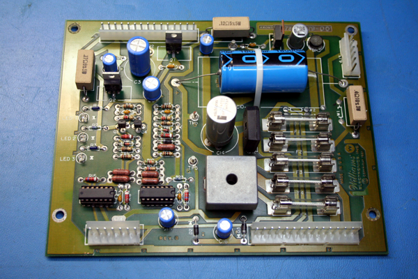
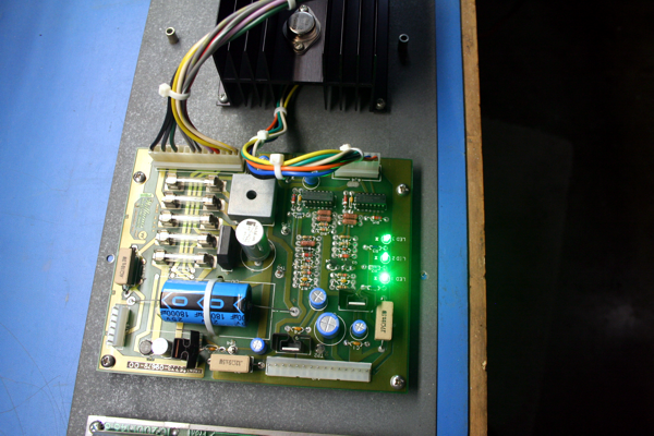
All components on this board are new. Outside the 18000uF cap, all the other caps are rated at 135C or higher. Most of the resistors are military grade. I also socketed the 723 ICs. I want this boardset to be rock solid and not have any issues for another 30 years (if I can help it).
Everything is working and the voltages are as expected. I swapped out those red LEDs for these green ones. I never understood why Williams put red LEDs in this board. To me, red indicates there is a problem. I like these green ones much better. With the power now taken care of, let's move on to the sound board.
Well, we moved to Florida and I've put the Robotron restoration on hold. I got the game working 100% and it's currently sitting in my office. But I would like to restore this cabinet once I get the shop built.
